5TM
- Manage
-
 Copy
Copy
- Actions
-
 Export
-
 Annotate
-
 Print Preview
- Viewers
-
 Source
-
 Siblings
-
 Attachments (1)
-
 History
-
 Likes
Likes
Overview
Decagon 5TM (Manufacturers webpage)
This sensor communicates digitally via the SDI-12 protocol. http://www.sdi-12.org/
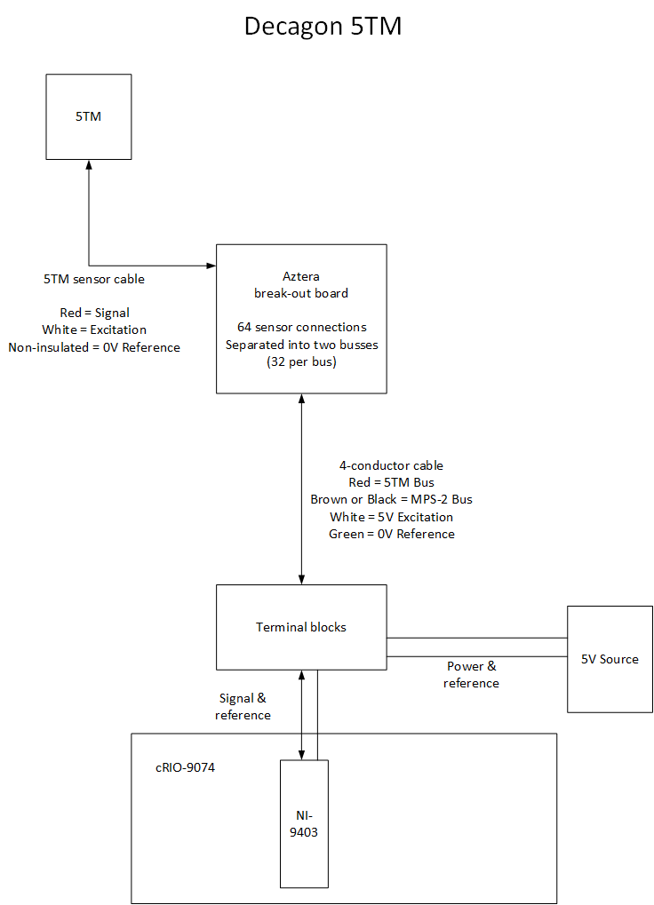
The cRIO in Panel 02 contains an NI-9403 high speed digital I/O module. The FPGA on the cRIO is programmed with a custom SDI-12 communications emulator. The module is capable of communicating with approximately 26 of the 32 digital buses simultaneously, this limit is aparently a hardware issue related to the impedance of the SDI-12 sensor network (basically the current draw to communicate with all those sensors is more than the module can provide). To combat this problem, the SDI-12 network is polled in two parts - all 5TM sensors, then all MPS-2 sensors.
The digital signal, when decoded, forms a simple ASCII text string which identifies the sensor address, the relative permittivity, and the temperature in degrees Celsius. An example output string is "B+7.5+25.6" - this shows sensor address "B", relative permittivity "+7.5", and temperature "25.6" Celsius.
The 5TM terminates to a custom junction board designed by Aztera (http://www.aztera.com/). The board provides a many-to-one junction for power, ground, and signal buses which allows for 32 SDI-12 sensors to be connected to a single signal bus.
Calculation Notes
| Sensor Code: | 5TM |
| Sensor: | 5TM from Decagon Devices Inc. |
| Measurement: | Volumetric water content (%) and Temperature (°C) |
| Output 1: | Apparent dielectric permittivity (unit-less) | Range 1: | 1 to 80 | |
| Output 2: | Temperature (°C) | Range 2: | -40 to 50 | |
| Output 3: | Range 3: | 0 to 50 |
C8 soil calibration as provided by Decagon Devices on August 15, 2011. Database uses coefficients A=17.8, B=40.9
Wiring Diagram