DVI7911 Junction Board
- Manage
-
 Copy
Copy
- Actions
-
 Export
-
 Annotate
-
 Print Preview
- Viewers
-
 Source
-
 Siblings
-
 Attachments (6)
-
 History
-
 Likes
Likes
Overview
The purpose of this board is to combine cabling of five (5) Davis Instruments anemometers into a pair (2) of 8-conductor cables and handle external circuitry required for data acquisition with these devices. Each Davis Instruments anemometer requires an excitation voltage of approximately 3.3 VDC and a pull-up resistor on the relay output of cup anemometer. A simple diagram of the internal circuitry of the Davis Instruments device is shown below:
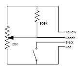
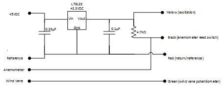
The normally open single pole single throw (NO-SPST) relay is actually a reed switch that closes for approximately 4ms when the cup anemometer passes the correct position. The potentiometer wiper is controlled by the wind vane. In order to monitor the junction box provides excitation regulation at 3.3VDC (from a 5VDC source), and pull up resistors for the reed switch. Below is the circuit diagram used on the junction board:
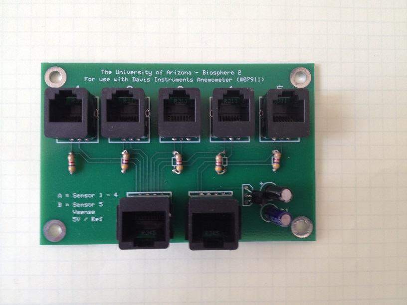
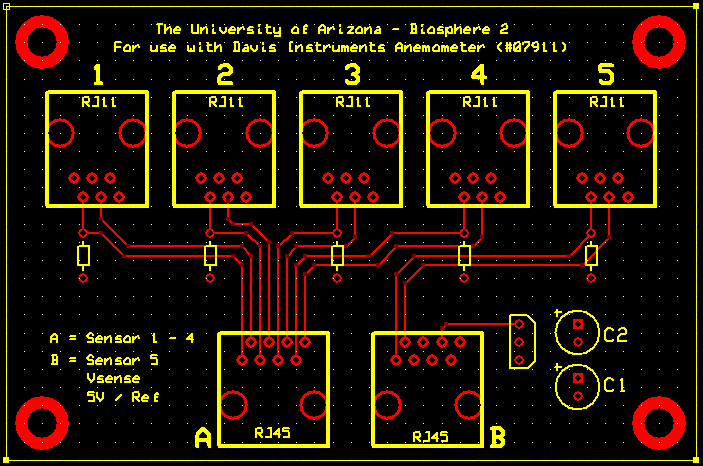
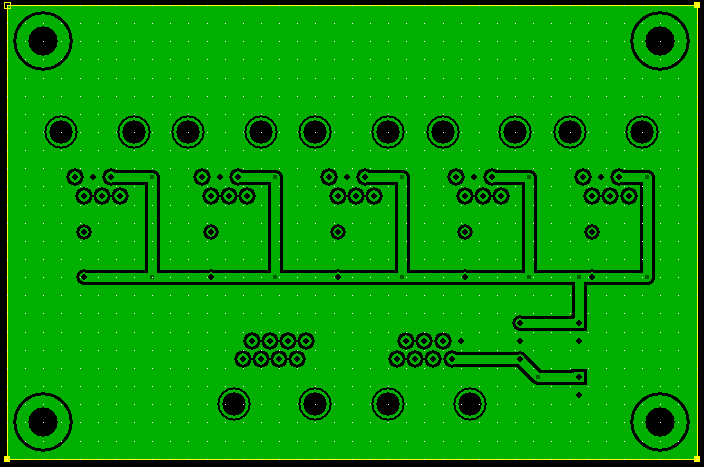
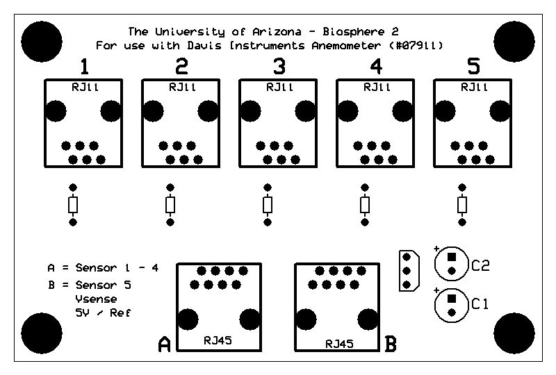
Images of the board, layout, and pin assignments
Pin assignment:
Plugs 1 through 5
- N/C
- +3.3VDC
- Potentiometer output
- Reference (Ground)
- Relay output
- N/C
Plug A
- Device 1 relay output
- Device 1 potentiometer output
- Device 2 relay output
- Device 2 potentiometer output
- Device 3 relay output
- Device 3 potentiometer output
- Device 4 relay output
- Device 4 potentiometer output
Plug B
- Device 5 relay output
- Device 5 potentiometer output
- N/C
- N/C
- N/C
- Voltage monitor (output of regulator)
- +5VDC (supply voltage)
- Reference (Ground)